Artifacts and misadventures in digital radiography
Images


Dr. Willis is an Associate Professor in the Department of Radiology, Baylor College of Medicine, Houston, TX. Mr. Thompson is a Medical Physicist with Memorial Medical Center, Modesto, CA. Mr. Shepard is a Senior Medical Physicist in the Department of Diagnostic Physics, University of Texas M.D. Anderson Cancer Center, Houston, TX.
This article is based on material originally presented in: Willis CE. Artifacts and misadventures in digital radiography. Presented at the Society of Computer Applications in Radiology Meeting. SCAR University Course 305, 20th Symposium. Boston, MA, June 710, 2003.
Considering the sales hyperbole associated with digital radiography (DR), one may wonder if it is even possible to produce a nondiagnostic digital image. Certainly DR is more tolerant of inappropriate exposure factor selection than is conventional film-screen radiology. However, classic technical errors (such as malpositioning, patient motion, incorrect patient identification, incorrect examination, and double exposure) still occur in the usual frequency.1 The unfortunate truth is that DR is subject to many of the same inaccuracies as conventional radiography, in addition to many new ones that are a direct result of the way the DR image is generated. An understanding of the causes of both new and old problems is necessary in order to avoid these inaccuracies and recover unacceptable images.
Artifacts and digital systems
An artifact is a feature in an image that masks or mimics a clinical feature. The literature classifies artifacts according to causative agent, such as hardware, software, or operator,2-5 although artifacts can also be categorized by the mechanism of interference with image acquisition, processing, or display.6 "Misadventures" encompasses the entire gamut of technical errors that can produce unsatisfactory images.
The reports cited above concentrated on computed radiography (CR), that is, any imaging system that relies on photostimulable luminescence to make a radiographic image. In contrast, this article also provides examples of problems that may be encountered with any DR system, including direct digital radiography (DDR) systems that make digital radiographs from the photoelectric interaction of X-rays with the detector itself, indirect digital radiography (IDR) systems that are sensitive to the light produced by an intensification screen, and optically coupled direct radiography (OCDR) systems that use optical components to focus fluorescence onto charge coupled detectors (CCD). In this context, DR includes any radiographic image acquired without photographic film, thus excluding film digitizers whose artifacts are described elsewhere.
DR systems
Digital radiographs in this study were produced with a variety of devices in clinical service at our institutions or available to us, including Agfa CR (Agfa Medical Systems, Ridgefield Park, NJ), Fuji CR (Fujifilm Medical Systems, Stamford, CT), GE DR (GE Medical Systems, Milwaukee, WI), and Canon DR (Canon USA, Inc., Lake Success, NY). Although not shown, we have similar experiences with Kodak CR (Eastman Kodak, Rochester, NY), Lumisys CR (now owned by Eastman Kodak), Konica CR (Konica Medical Imaging, Inc., Wayne, NJ), and Hologic DR (Hologic, Inc., Bedford, MA).
Acquiring good quality images
Regardless of the acquisition technology, good radiographic images can be produced only when certain fundamental requirements are met. Appropriate radiographic technique must be used, which includes the proper tube potential (kVp), beam current (mAs), source-to-image distance (SID), collimation, alignment of the X-ray central ray, and positioning of detector and subject for the specific anatomic projection.
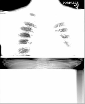
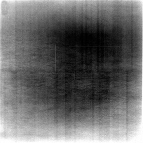
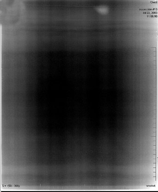
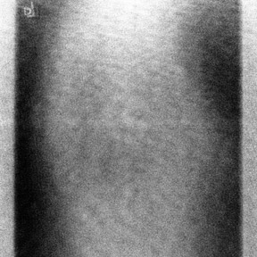
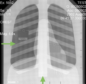
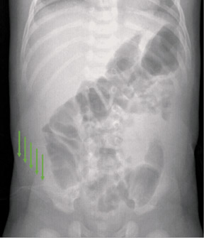
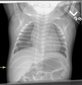
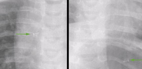
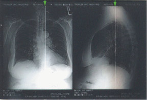
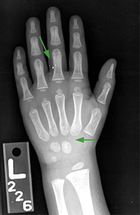
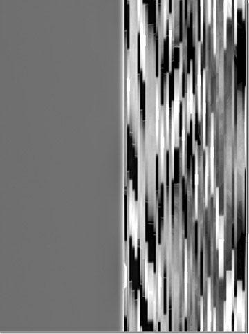
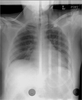
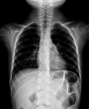
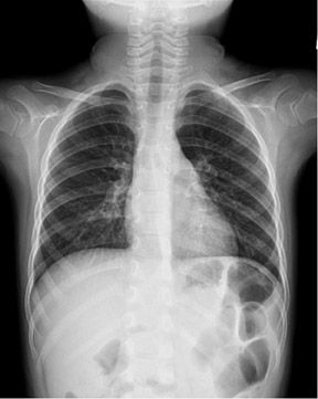
The detector must receive enough X-rays to make a good image.7 Whether from underexposure or misalignment of a scatter reduction grid, too few X-rays produce noisy images (Figures 1 and 2). Too many X-rays are a disservice to the patient and may also produce poor images (Figure 3). Although DR is more tolerant of incorrect exposure factor selection, it cannot make up for extra noise, loss in subject contrast, and signal out of its range of adjustment.
"Exposure factor creep" is a well-known phenomenon related to the wide exposure latitude of DR.8,9 Observers tend to complain about noise in DR images exposed at one-fourth to one-half of the appropriate level. On the other hand, artifacts are generally not apparent until the exposure exceeds 10 times the appropriate level. Technologists soon learn to avoid the unpleasant circumstance of repeating an underexposed study by routinely increasing the radiographic technique. Thus, the potential for gross overexposure exists in DR. Image optical density (OD), the usual indicator of proper exposure, is arbitrary in DR. Managment of exposure factor in DR must rely on the value of a derived exposure indicator, which itself is subject to interference. However, programs that monitor the exposure indicator have been shown to be effective in controlling exposure factor in DR.10
System installation and maintenance
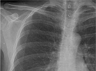
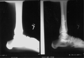
In order to make good images, the DR device must be properly calibrated, configured, maintained, and operated. Every individual DR device must be calibrated for overall gain and uniformity.11 This is usually performed during the initial installation and should be repeated periodically. Acquisition devices should be calibrated for gain or sensitivity, and to compensate for nonuniformity (Figures 4 and 5). Display devices should be calibrated to provide output according to the DICOM Part 14 Grayscale Display Function, including hard-copy devices, soft-copy devices, and displays used for quality control (QC).12 Processing algorithms used by the DR system must be designed to anticipate the use of this display function in order to properly render the image for display. Not all vendors adhere to this standard. Calibrated, high-quality QC monitors are essential on every acquisition system and QC workstation. Adjusting image processing on an uncalibrated monitor leads to unsatisfactory images.
During the initial installation, it is important to make sure that the DR system is properly configured with the most up-to-date version of software, hardware, and durable goods. Multiple vintages of imaging plates exist for CR, and some are not universally compatible with CR hardware. The software and settings should be consistent with the versions and settings in operation with other individual DR systems at the site, including examination-specific parameter settings (Figure 6). All DR systems have an internally calculated estimate of exposure. The DR system may need to be configured to report this value to the digital image management system, and the image management system may need to be configured to display it to the radiologist. When CR is introduced into an imaging operation, phototimers in all X-ray rooms need to be recalibrated to deliver the appropriate exposure.13 The methodology for phototimer calibration is different because DR density is adjustable.
Scheduled and unscheduled service should be done in a thorough and timely manner, including reporting and documenting, cleaning, and repairs. Operator functions include cleaning, reporting service interruptions, removing the unit from clinical service, re-introducing the unit into clinical service, and documenting service events (Figure 7). Service engineer functions include performing scheduled maintenance that includes preventive maintenance and software and hardware upgrades, as well as unscheduled maintenance or repairs. On-site support for DR requires a team with expertise not only in image acquisition, but in picture archiving and communications systems (PACS), radiology information systems (RIS), technologist workflow, image quality, and networks, as well.
Training and system operation
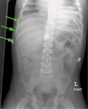
Digital radiography systems must be operated properly to produce good images. Technologists are often unfamiliar with DR features and functions, and may require additional training beyond vendor applications training. Technologists need to select the proper examination; in addition, they must properly associate demographic and examination information to the image, properly manipulate the detector, and review the image before releasing it to the image management system. Beyond this, technologists need to know how to recover from errors without repeating examinations and need to follow exposure factor control limits. Quality control processes must be in place to detect and correct unsatisfactory images (Figures 8, 9, and 10). Digital radiography requires a new approach to QC and study reject analysis.14 Electronic images can disappear without a trace: counting the films remaining in the film bin is no longer a useful method for determining the number of repeated images.
Double exposure is a classic operator error that constitutes approximately 2% of all rejected images. The consequence of double exposure can be either a single repeated examination, when an inanimate object is involved (Figure 11), or two repeated examinations when two patients are involved (Figure 12). In DR, double exposures can also be caused by power interruptions and communications errors, as well as by inadequate erasure secondary to overexposure or erasure mechanism failure.
Image processing
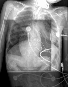
Appropriate digital image processing is key to producing good DR images. All DR systems have extremely wide latitude, which means that connected to a display system with a relatively narrow dynamic range, DR images have extremely low contrast. The primary purpose of image processing is to maximize the contrast of the part of the image that contains relevant clinical details.15,16 To do this, the DR system locates either the boundary of collimation or the border of the projected anatomy, and disregards details outside this boundary. Errors in collimation can cause mistakes in detection of the boundary, with a dramatic loss of image contrast (Figures 13 and 14).
The secondary function of image processing is to customize contrast in the region of interest (Table 1). This type of image processing includes modifying the image to enhance the contrast and sharpness of some features while compromising the contrast and sharpness of others, as well as modifying the image to make it appear more like a conventional transilluminated film. This secondary image processing is applied in a manner that is usually specific to the anatomic projection. Errors in the selection of the anatomic projection can cause inappropriate processing (Figure 15).
An auxiliary purpose of image processing is to improve the usability of the digital image.17 This includes imprinting demographic overlays, adding annotations, applying borders and shadow masks, flipping and rotating, increasing magnification, conjoining images for special examinations like scoliosis, and modifying the sequence of views. This processing may require a separate QC workstation.
Image processing is not a panacea. Misuses of image processing include compensating for inappropriate radiographic technique, compensating for poor calibration of acquisition and display devices, and surreptitious deletion of nondiagnostic images. Image processing to recover nondiagnostic images to prevent re-exposure should be a last resort, not a routine activity. Routine reprocessing indicates a problem with automatic image processing or technical practice. Access to image-processing software is essential to develop and maintain appropriate processing parameters.
Automatic image processing involves assumptions about the radiographic technique, the composition of anatomic region imaged, and the use of collimation. A number of factors can interfere with the automatic detection of the boundaries of the radiation field, including nonparallel collimation, use of multiple fields on a single imaging plate, poor centering, implants (especially when they overlie the boundary), and violation of collimation rules provided by the vendor. For example, placement of gonadal shields is no longer trivial, but may adversely affect image quality.
Conclusions
A multitude of factors affect DR image quality, and no device or operator is immune to unacceptable images. A strategy for addressing images that "just didn't turn out right" must be implemented. Responsibilities for documenting, reporting, and taking corrective action must be clearly established. Wider dynamic range means that technologists have to pay attention to exposure indicator values, instead of brightness and contrast. Without this attention, patient dose will escalate. If exposure indicator logs are available, they need to be evaluated. If they aren't, this will need to be done manually. Vendors need to make such logs available in convenient digital form. New technologies should be developed for dealing with pediatric examinations and patients with prosthetic devices. New image processing strategies may be needed with these special patients, as well.
Thorough training and active onsite support of the technical staff are crucial. For many, this is a completely different way of thinking about the imaging process. Technologists are generally eager to become involved and master this new technology, but they need proper training and guidance to use it effectively to produce diagnostic-quality images.
References
1. Willis CE, Mercier J, Patel M. Modification of conventional quality assurance procedures to accommodate computed radiography. Presented at the 13th Conference on Computer Applications in Radiology. Denver, Colorado. June 7, 1996: 275-281.
2. Oestmann JW, Prokop M, Schaefer CM, Galanski M. Hardware and software artifacts in storage phosphor radiography. RadioGraphics. 1991;11:795-805.
3. Solomon SL, Jost RG, Glazer HS, et al. Artifacts in computed radiography. AJR: Am J Roentgenol. 1991;157:181-185.
4. Volpe JP, Storto ML, Andriole KP, Famsu G. Artifacts in chest radiography with a third generation computed radiography system. AJR: Am J Roentgenol. 1996;166:653-657.
5. Tucker DM, Souto M, Barnes GT. Scatter in computed radiography. Radiology. 1993;188:271-274.
6. Willis CE. Computed radiographic imaging and artifacts. In: Seigel EL, Kolodner RM, eds. Filmless Radiology. New York, NY: Springer-Verlag; 1999:137-154.
7. Huda W, Slone RM, Belden CJ, et al. Mottle on computed radiographs of the chest in pediatric patients. Radiology. 1996;199:249-252.
8. Freedman M, Pe E, Mun SK, et al. The potential for unnecessary patient exposure from the use of storage phosphor imaging systems. SPIE. 1993;1897:472-479.
9. Gur D, Fuhman CR, Feist JH, et al. Natural migration to a higher dose in CR imaging. Presented at the Eighth European Congress of Radiology. Vienna, Austria. Sep 12-17, 1993:154.
10. Seibert JA, Shelton, DK, Moore, EH. Computed radiography X-ray exposure trends. Acad Radiol. 1996;4:313-318.
11. Willis CE. Computed radiography: QA/QC. In: Seibert JA, Filipow LJ, Andriole KP, eds. Practical Digital Imaging and PACS. Medical Physics Monograph No. 28. Madison, WI: Medical Physics Publishing; 1999:157-175.
12. Thompson SK, Willis CE, Krugh KT, et al. Implementing the DICOM Grayscale Display Function for Mixed Hard- and Soft-copy Operations. J Digital Imaging. 2002;15(suppl 1):27-32.
13. Christodoulou EG, Goodsit MM, Chan H, Hepburn TW. Phototimer setup for CR imaging. Med Phys. 2000;27:2652-2658.
14. Blado ME, Ma Y, Corwin RA, Carr SG. Impact of repeat/reject analysis in PACS. J Digital Imaging. 2003;16(suppl 1):22-26.
15. Chotas HG, Ravin CE. Digital radiography with photostimulable storage phosphor: Control of detector latitude in chest imaging. Invest Radiol. 1992;27:822-828.
16. Huda W, Slone RM, Arreola M, et al. Significance of exposure data recognizer modes in computed radiography. SPIE. 1996;2708:609-616.
17. Willis CE. Quality assurance: An overview of quality assurance and quality control in the digital imaging department. In: Reiner BI, Seigel EL, Carrino JA, eds. Quality Assurance: Meeting the Challenge in the Digital Medical Enterprise. Great Falls, VA: Society for Computer Applications in Radiology; 2002:1-8.
Related Articles
Citation
Artifacts and misadventures in digital radiography. Appl Radiol.
January 28, 2004