Digital radiography quality assurance: A technique for standardizing image appearance across CR and DR platforms


Dr. Koenker is the Radiology Director, Novato Community Hospital, Novato, CA.
Hospitals and imaging centers commonly use a mixture of digital radiography techniques such as direct radiography (DR), computed radiography (CR), and mobile DR. Frequently, physicians encounter challenges when comparing DR and CR images because of inherent differences in the overall image attributes. These challenges occur because of different settings in brightness, gray-scale latitude, harmonized contrast, and edge enhancement. 1 Adding further variability, physicians may view inpatient images from a CR system manufactured by one vendor and outpatient images from a CR system from another manufacturer. This variety in image appearance has medical implications, since clinicians prefer to assess patient treatment progress based on an "apples-to-apples" comparison of images. 2 In the ideal clinical situation, image appearance differences resulting from the use of various radiography platforms should be minimized. 3
On occasion, radiologists notice that "the image just doesn't look right." The cause of inconsistent image quality can originate from many possible sources, including cassette erasure difficulties, CR reader problems, processing algorithm issues, and display monitor deviations. 4 Since there are many potential sources for image quality difficulty, a quantitative method to define and establish a "quality reference image" is needed.
For these reasons, a step-by-step description of a technique to standardize the appearance of images across platforms would be useful. The obvious solution to this problem would be to copy and export postprocessing settings from device A to device B. However, this solution works only when exporting settings among identically designed devices (eg, a CR system of one vendor with another CR system from the same vendor). When cross-platform standardization is attempted, simply copying software settings does not work because of the numerous variables (eg, system gray-scale bit depth and detector sensitivities) that are encountered when moving from one platform to another. 5
This article describes a method whereby measurements of brightness at various key image points can be used to standardize the visual characteristics of CR and DR radiographs. This technique is important when attempting to optimize clinical decision-making when a DR image obtained at time point "A" is compared with a subsequent CR image at time point "B."
Background:The imaging chain
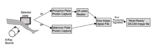
To understand the key contributing steps to the overall radiograph appearance, a chain-of-events block diagram is useful. Figure 1 outlines the steps in the imaging chain from X-ray exposure to image presentation for both CR and DR techniques. The goal is to provide a "read-ready" image with consistent at-tributes (eg, similar gray-scale latitude, edge enhancement, and brightness) regardless of whether the image followed the DR or the CR chain. Notably, the steps of X-ray photon capture and detector plate readout in CR are inherently different from those steps in DR. As a result, the raw image digital files will look quite different for these two imaging chains; however, skillful adjustment of the postprocessing algorithm settings can provide a means to correct the raw image data. 6
Tools for comparing digital systems: Phantoms and luminance meters
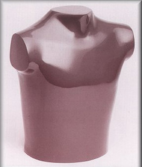
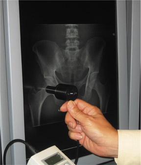
To facilitate adjustments to the image-processing algorithms, the object being radiographed must remain constant. 7 This is readily accomplished using commercially available anthropomorphic phantoms (Figure 2). Generally, a full-size chest phantom and a full-size pelvis phantom can meet the needs of most centers. Images were obtained using standard radiographic methods in both the DR and CR rooms of our hospital (Novato Community Hospital, Novato, CA). Using such phantoms as controls, it is possible to compare and adjust the image characteristics of various systems. 8 After initially matching the image settings using subjective impressions in our department, the standardized look was further defined using luminance meter measurements obtained directly from the soft copy view station display (Figure 3). These types of measurements provide an accurate yardstick for adjusting the gray-scale latitude.
How to standardize your images: A step-by-step process
Step 1: The "lead" radiologist chooses a preferred processing "look" based on a review of several radiographs from the institution. This is a subjective endeavor, which is easily accomplished, since there is usually one radiographic system within the enterprise that produces images that are preferred by most of the radiologists. Based on this image review, the radiologist selects a favored "reference" image latitude and brightness.
Step 2: A phantom is radiographed and digitally processed using the preferred processing parameters. This reference image is then sent to a picture archiving and communication system (PACS), where the image can serve as a "gold standard" against which images from other systems can be compared.
Step 3: The phantom is then radiographed on the other systems at the hospital, and images are sent for review on a PACS workstation with medical-grade gray-scale LCD panels. At our institution, the workstations (MagicView 1000U PACS, Siemens Medical Solutions, Malvern, PA) are set up with DOME C3 monitors that are calibrated to the DICOM standard with DOME CXtra calibration software (Planar Systems, Inc., Waltham, MA).
Step 4: Initial adjustments to the image appearance are made using subjective assessment of the images during a coordinated effort between an application specialist who is familiar with the radiography system and a radiologist who is experienced with digital image interpretation. The goal is to "tweak" the secondary system's processing settings so that images roughly match the agreed-upon favored reference image.
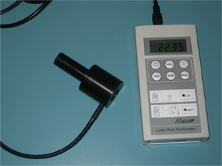
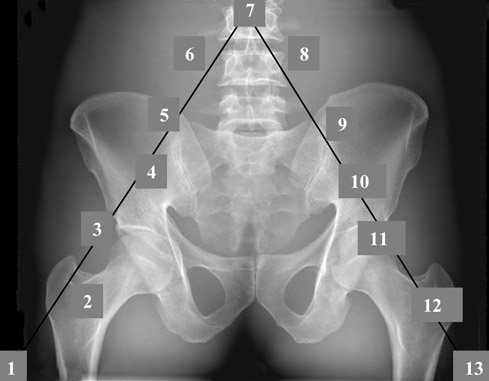
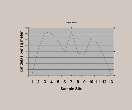
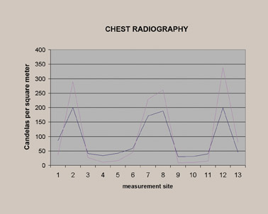
Step 5: Final adjustments to the secondary system are then made using quantitative luminance measurements (Figure 3) obtained by a photometer (in our case, an L202 PMS Photometer, Macam Photometrics Ltd., Livingston, Scotland) that provides readings directly from the display monitor. These measurements are obtained from 13 locations on the image (Figure 4), and the measurement values can be graphically displayed on a chart (Figure 5) that shows candelas per meter squared (cd/m 2 ) versus the sample site.
Step 6: Through coordinated efforts by the application specialist, the luminance curves of the secondary system are then brought almost to superimposition with the favored reference system image by fine-tuning the postprocessing algorithms. Once the final algorithm is selected, the settings are engaged as the default algorithms for the imaging system.
The goal: CR/DR images that look similar
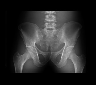
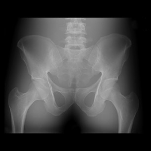
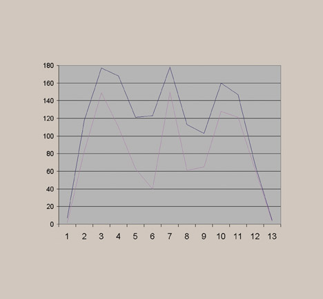
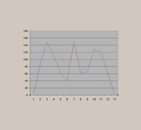
Before standardization, the radiographs of the pelvis looked significantly different, especially regarding the gray-scale latitude (Figure 6). This subjective finding was confirmed by photometer measurements (Figure 7). As described above, a favored reference appearance was selected (in this case, the DR image was chosen), and adjustments were made so that other images would match in overall gray-scale and harmonized contrast characteristics (Figure 8). This matched appearance is possible even though images came from both CR and DR machines. The photometer measurements can confirm, on a quantitative basis, a similar image appearance as documented by improved superimposition and overlap of the brightness measurement curves (Figure 9). This process was repeated for several other common examinations, such as lumbar spine, hip, and chest. Figure 10 shows the improved visual results after adjustments for the chest radiographs, for which significant improvement in the luminance curve overlap was accomplished after normalizing the overall image appearance (Figure 11).
Discussion
Historically, within a specific platform (eg, a CR system from a single vendor), images look the same whether the study came from machine A on the first floor or machine B on the second floor of the radiology department. However, any large healthcare enterprise will use several different platforms for obtaining digital radiographs, and these hardware differences will likely include a mixture of CR and DR systems. Some installations may even have multiple vendors providing these radiographic modalities. Because of differences in image quality and appearance, it is important to make the image appearance consistent across digital radiography systems. 9
There are many factors that influence image appearance, including exposure characteristics (mAs and Kvp), the use of an antiscatter grid, and properties of the phosphor versus selenium detector plates. 10,11 It is equally important to make preprocessing adjustments to the histogram during plate readout and adjustments to the postprocessing algorithms, which are frequently anatomy-specific. Both pre- and postprocessing influence the final appearance by dictating the edge enhancement, gray-scale latitude, window-level settings, and harmonized contrast. Finally, from an observer's viewpoint, the characteristics of the display monitor also play a role-ie, there is a noticeable difference between medical-grade high-brightness, high-contrast gray-scale LCD monitors and noncalibrated, off-the-shelf, low-brightness color monitors.
Given this complex chain of events (Figure 1), it is not practical to simply export a collection of settings to provide for cross-platform uniformity of image quality throughout the enterprise. While some radiologists and engineers believe that DR provides better image quality, 12 as measured by the conspicuity of important findings such as calcified and noncalcified lung nodules, 13 others have observed that it is possible to compensate for the physical differences in detector characteristics with the use of advanced postprocessing algorithms (such as UNIQUE [UNified Image Quality Enhancement], Philips Medical Systems, Best, The Netherlands). This type of processing algorithm provides for harmonized contrast throughout the image, with particular enhancement in areas of faint contrast. 14
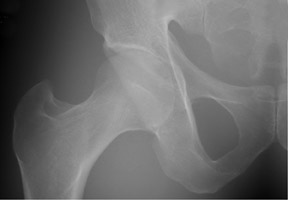
The importance of carefully selecting and tuning the postprocessing algorithms is shown in Figure 12. In this example, before optimization, the hip radiographs had a wide latitude appearance. Although that appearance was adequate for diagnosis, conspicuity of abnormal findings was not optimized. The final product image, after adjustments of the postprocessing settings, shows a view that renders anatomic structures with better contrast and conspicuity of important regions and findings.
With the help of an application specialist, it is possible to test the appearance of an identical subject in step 1 of the imaging chain (Figure 1) through the use of a phantom. In turn, the end point of the imaging chain can be assessed both subjectively and objectively using the techniques described in this article, with the goal of normalizing and standardizing image quality across platforms.
Although experienced interpreters can mentally compensate for processing technique differences between images, it requires additional subjective mental interpolation of images. As a result, a comparison of 2 different studies from 2 different time points becomes less accurate and less intuitive. This can be especially challenging for observers (eg, referring physicians) who do not practice these types of subjective interpolations. Certainly, it is possible to partially adjust and normalize the image appearances using standard window/level adjustments on viewing stations. However, anatomy-specific postprocessing presets should provide physicians with images that are "read-ready" and, accordingly, require only minimal end-user manipulations.