Digital radiography: CR versus DR? Sometimes recognizing the distinction in technologies makes a difference
Images
Dr. Willis is an Associate Professor, Department of Imaging Physics, The University of Texas M.D.Anderson Cancer Center, Houston, TX.
There is no doubt that all digital radiographic images share many characteristics regardless of the technology with which they are acquired simply because they are all digital approximations of an analog projection. This is true even of older forms of digital radiographs, eg, digitized films and charge-coupled devices (CCD) mated to X-ray–to–light converters. All digital radiography (DR) devices have limitations with respect to spatial resolution (sharpness) and contrast resolution because of the finite dimensions of their detector elements (dels) or picture elements (pixels). All digital imaging devices are subject to certain artifacts such as aliasing, moiré patterns, and contouring because their images are an array of elements with finite dimensions and quantization. All digital imaging devices separate the process of acquisition from display and thus allow modified rendering of the image for viewing. Digital radiography devices typically have wide latitude, which results in low contrast if the digital image is mapped to a display device of limited latitude without appropriate rescaling. Recent variants of digital radiography cross traditional boundaries between receptor technologies. A review of the basics of large field-of-view digital detectors predicted that:
“Unfortunately, it is also likely that there will be a tendency to think of these devices as equivalent, interchangeable commodities because they are similar in physical size, appearance, and targeted applications. It must be emphasized, however, that important differences exist among these detectors, and differences in digital image quality among the various systems are inevitable and may be quite large. To minimize confusion, therefore, it is important for radiologists to have a working understanding of this emerging technology.”1
Computed radiography (CR) was the product name for the first commercial device for making radiographs using the process of photostimulable luminescence (PSL), whereby X-ray energy projected onto a doped crystalline material—the photostimulable phosphor (PSP)—produces a latent image of excited electrons in local potential energy traps.2 The number and locations of these excited electrons is a faithful representation of the original projected X-ray energy. The electrons are released from their traps by stimulation with light of a specific wavelength (photostimulation). The electrons de-excite by the release of photostimulable light (PSL), which can be measured and digitized to create a digital image.
Rather than being the product, the digital image was an intermediate in the process of making a laser-printed film image for interpretation. The incentive for a film company to introduce such a device was that by using a single receptor type, a single receptor processor, a single laser film, and a single laser film processor, the characteristic speed, contrast, and latitude of any screen-film combination could be simulated by manipulating the digital image and could be duplicated as desired. The receptor could be erased with white light and reused to acquire another projection. Advances in automation and information technology soon made the digital image more desirable than the laser films. Recent improvements in CR acquisition speed and integration are the basis for the argument that CR should no longer be distinguished from DR.
The CR cassette form factor contributed to the rapid acceptance of CR as a digital imaging modality. CR systems built into upright exposure stations and examination tables existed as competing products with cassette-based CR systems almost from the beginning of the technology. Only recently have the terms “integrated” or “cassetteless” been introduced to distinguish this type of system from cassette-based CR. Perhaps the most important aspect of integration is the possibility that the receptor system may share information about how the radiographic projection was generated.
The traditional method for developing the CR latent image was to use a laser beam “flying-spot” that was deflected by an alternating mirror across the advancing PSP imaging plate in a raster fashion.3 Stimulated light was collected and directed onto ≥1 photomultiplier tubes, whose analog currents were converted into digital signals. The timing of the analog-to-digital conversion in concert with the relative motion of the laser spot and plate determined the spatial relationship of each digital pixel value.
The line scan is a new method of developing the CR image, which relies on an array of laser diodes and CCDs that move across the PSP imaging plate stimulating and reading the image in a rapid fashion. These arrays can be made small enough to fit inside a cassette or in an integrated CR system. Ironically, an early (circa 1987) integrated CR system for chest imaging, the Konica Direct Digitizer (KDD), incorporated a linear scanning mechanism (rather than advancing the PSP imaging plate) and used a special PSP material that had an extremely short luminescence rate and concomitant rapid spontaneous fading of the latent image. The KDD mechanism used a solid state laser and galvanometer to deflect the beam.
Despite improvements in speed and integration, CR remains distinct from other forms of digital radiography. It is difficult to imagine how PSP imaging could ever be rapid enough to acquire images at 30 frames per second, as needed for fluoroscopy, which is within the capabilities of other digital radiography devices. There is no latent image in non-CR digital radiography, unless perhaps one considers the charges prior to readout by the semiconductor arrays. There was a latent image in selenium drum DR systems, in the form of unsatisfied charges remaining after exposure to ionizing radiation. There is no possibility of double exposures in DR, but they can occur in CR if the PSP is exposed a second time before it is developed. Because PSL occurs over a finite time after stimulation, there is always an additional source of blur (unsharpness) in the direction of laser or laser array motion. This sort of anisotropic blur is not present in DR systems, which have discrete detector elements fixed in space.
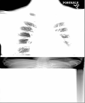
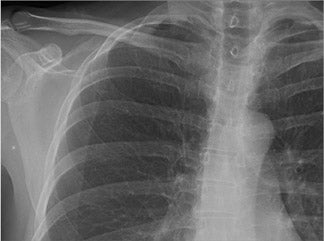
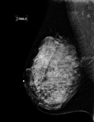
Because CR involves mechanical motion, there is always the possibility of interference with the mechanical advance of the PSP imaging plate, laser deflection mechanism, or scanner array; such interference manifests in artifacts (Figure 1). In general, DR devices are based on semiconductor arrays that are fixed in space and are read without mechanical motion. Slot scanning or fan-beam DR devices are an exception to this general rule.
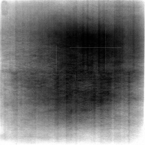
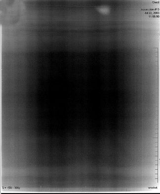
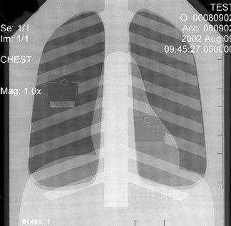
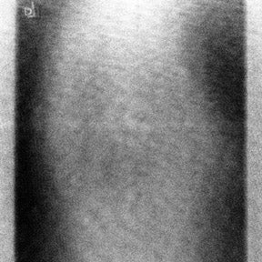
There is a fundamental difference in the purpose and manner of gain and offset correction in DR and the non-uniformity correction in CR (Figure 2). In CR, differences in stimulation and light collection efficiency are generally corrected in 1 dimension. In DR, not only must the gain and offset of each del be equalized, but the presence of defective dels must also be compensated for by averaging neighboring dels.4 Newly defective dels in DR and interference with light collection in CR manifest differently in the digital image (Figure 3).5
There are differences in the durability and replacement costs for CR receptors versus DR receptors. Except for the newest structured phosphor CR receptors, physical impact is not as much a concern for CR receptors, and their cassettes can be replaced or repaired. Photostimulable phosphor imaging plates are subject to processes of mechanical damage and chemical oxidation but can be replaced at a nominal cost. DR receptors do not last forever; they are subject to slow aging processes, and their replacement cost is a substantial portion of the capital investment for the total system.
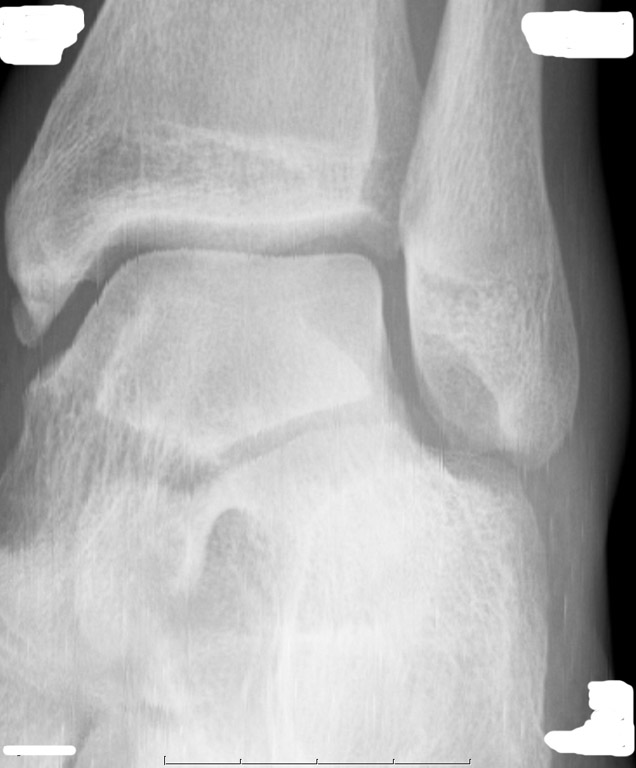
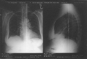
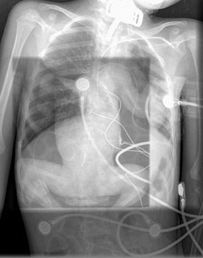
“Lag” and “ghosting” processes in DR do not exist in CR. These false images arise from residual signal in the X-ray–to–light conversion layer or from residual charge in the thin-film transistor itself.6-8 These are very different from inadequate erasure and double exposure in CR (Figure 4).
CR imaging plates are integrating dosimeters. Until they are read or erased, they continue to build up charge from background radiation or scattered radiation. This fogging process has not been reported for DR detectors. Likewise, since DR images are immediately read-out, fading processes that can occur for CR have not been reported for DR.
CR was introduced into clinical practice 2 decades ago. As a result, processing of the digital image in CR is more mature, more clearly defined in the literature, and more clinically proven than it is in any commercial DR system. Examples of image processing being exported wholesale from CR onto DR detectors without any modification or customization can be found among some commercial systems. It would be serendipitous if the processing that was developed for a specific CR receptor were appropriate for any detector with different fundamental properties, such as the mechanism of image formation, the sources and characteristics of noise, and details such as matrix size, gray-scale bit depth, and characteristic function.
Owing to the early introduction of CR into clinical practice, CR exposure indicators for CR are better documented and more useful than those for DR. Notwithstanding standardization efforts for a receptor exposure indicator suitable for both CR and DR by the American Association of Physicists in Medicine (AAPM) TG 116 and the International Electrotechnical Commission (IEC), current literature describes CR exposure indicators, provides target ranges, explains how they can be used for patient dose management purposes, and describes potential interferences.9 Such information about DR exposure indicators is scant.
Again, because of the maturity of CR as a clinical modality, performance and quality measurements have been established for CR10 but not yet for DR. AAPM TG 150 represents the beginning of an effort to establish such metrics, but this only began in 2007.
There are some historical arguments for retaining the CR nomenclature for PSP imaging systems. There are 20 years of scientific literature describing performance characteristics and clinical uses of CR that would not be found by a search engine when using “DR” as the key field.
The naming of DICOM Modality Objects also obscures the differentiation between CR and DR. The “CR Object” was an early and primitive object for digital radiographic images. The “DX Object” was developed later to correct some of the shortcomings of the CR Object. As a result of its late development, and because some PACS vendors were slow to accommodate the DX Object, some DR vendors adopted and still use the CR object. There are many benefits to using the DX Object, for both CR and DR images; therefore, both CR and DR vendors should migrate to the DX Object.
Conclusions
All digital radiographic images share many characteristics that are inherent to their discrete approximation of a plane projection of X-rays through anatomy that is continuously variable with respect to intensity and spatial distribution. A variety of receptors have been applied to the task of acquiring a digital radiography. The convergent evolution of form and function of these devices has led many to conclude that distinctions between CR and DR serve no useful purpose. Although categorization of CR as part of the umbrella of DR is tempting and contributes to a broader view of digital radiography, there are specific reasons why CR should be considered a separate imaging modaity. Similar reasons may exist for maintaining distinctions for other receptor technologies. Perhaps an alternative nomenclature that would include CR and all forms of DR might be electronic radiography.
REFERENCES
- Chotas HG, Dobbins JT 3rd, Ravin CE. Principles of digital radiography with large-area, electronically readable detectors: A review of the basics. Radiology.1999;210:595-599.
- Rowlands JA. The physics of computed radiography. Phys Med Biol.2002;47:R123-R166.
- Schaetzing, R. Computed radiography technology. In: Samei E, Flynn MJ, eds. Advances in Digital Radiography.RSNA Categorical Course in Diagnostic Radiology Physics. Oak Brook, Ill: Radiological Society of North America; 2003:7-21.
- Seibert JA, Boone JM, Lindfors KK. Flat-field correction technique for digital detectors. Proc SPIE.1998;3336:348-354.
- Willis CE, Thompson SK, Shepard SJ. Artifacts and misadventures in digital radiography.Appl Radiol.2004;33(1):11-20.
- Yorkston J. Flat-panel DR detectors for radiography and fluoroscopy. In: Goldman LW, Yester MV, eds.Specifications, Performance Evaluations, and Quality Assurance of Radiographic and Fluoroscopic Systems in the Digital Era.Madison, WI: Medical Physics Publishing; 2004:177-228.
- Kabir MZ, Yunus M, Kasap SO. Dependence of x-ray sensitivity of direct conversion x-ray detectors on x-ray exposure and exposure history. In: Yaffe MJ, Flynn MJ.Medical Imaging 2004: Physics of Medical Imaging.Proc SPIE.2004;5368:170-176.
- Siewerdsen JH, Jaffray DA. A ghost story: Spatio-temporal response characteristics of an indirect-detection flat-panel imager. Med Phys.1999;26:1624-1641.
- Seibert JA, Shelton DK, Moore EH. Computed radiography X-ray exposure trends. Acad Radiol.1996;3:313-318.
- Seibert JA, Bogucki TM, Ciona T, et al.Acceptance Testing and Quality Control of Photostimulable Storage Phosphor Imaging Systems:Report of AAPM Task Group #10.American Association of Physicists in Medicine Report 93. New York, NY: American Association of Physicists in Medicine; 2006.